30SI Series and 34SI Series Alternator - SENR7508
General Information
SMCS - 1405
Often when problems with the charging system are being investigated, the alternator is not the problem. If a low battery condition is present, test the batteries first. See Special Instruction, SEHS7633, "Battery Test Procedure" for more information. If the engine cranks slowly, then test the starting system. See Service Magazine, SEPD0020, "Testing The Starter On The Engine" for more information. If a warning indicator for the charging system is ON, see Service Magazine, SEBD1751, "Difference Between Alternator Indicator In Electronic Monitoring System (EMS) And Low Voltage Indicator In Operating Monitoring System (OMS)". When a problem with the charging system is suspected, then complete the testing that is outlined in this Special Instruction.
See Troubleshooting, "Initial Troubleshooting Procedure" in order to begin troubleshooting. These procedures are designed to guide you to the problem with as little testing as possible. In most cases, you will only use a few of the tests to diagnose a problem. The tests are labelled as T1 - T8 for easy reference. A descriptive title for each test is included as well.
Initial Troubleshooting Procedure
SMCS - 1405; 7569
- CHECK THE SYSTEM VOLTAGE.
- Before you start the machine, connect a voltmeter between the "B+" terminal and the case of the alternator. Turn OFF all electrical loads.
- Turn the key to the ON position but do not start the engine.
Expected Result: This voltage should be system voltage.
Results:
- YES - The voltage is system voltage. Go to Step 2
- NO - The voltage is less than system voltage. Verify that the batteries are good and verify that battery connections are good. Go to Troubleshooting, "T4 Alternator Drive System - Check" if the batteries are good.
- YES - The voltage is system voltage. Go to Step 2
- INITIAL CHECK OF ALTERNATOR OPERATION
- The voltmeter remains connected in the configuration from Step 1.
- Start the machine. Set the throttle to at least 75%. Read the voltage on the voltmeter.
Expected Result: The voltage is higher than the voltage recorded in the previous Step 1.
Results:
- YES - The voltage is higher than the voltage observed in the previous Step 1. The voltage is also lower than the maximum voltage that is listed in the specifications for the alternator. The alternator is partially charging the battery. See the following diagnostic flow chart for reference in continued testing. Proceed to Troubleshooting, "T1 Alternator Output - Test".
- YES - The voltage is higher than the voltage observed in the previous Step 1. The voltage is also higher than the maximum voltage that is listed in the specifications for the alternator. The alternator is over charging. Proceed to Troubleshooting, "T8 Alternator Overcharging - Test".
- NO - The voltage is not higher than the voltage observed in Step 1. Proceed to Troubleshooting, "T4 Alternator Drive System - Check".
- YES - The voltage is higher than the voltage observed in the previous Step 1. The voltage is also lower than the maximum voltage that is listed in the specifications for the alternator. The alternator is partially charging the battery. See the following diagnostic flow chart for reference in continued testing. Proceed to Troubleshooting, "T1 Alternator Output - Test".
Note: Severely discharged batteries can cause low system voltage. This can occur even while the engine is running above idle, and the alternator is working properly. Proper low engine idle is also important. The alternator is self-excited. Self-excited alternators must exceed a turn-on speed before the battery will charge. Alternator output can be very low at idle.
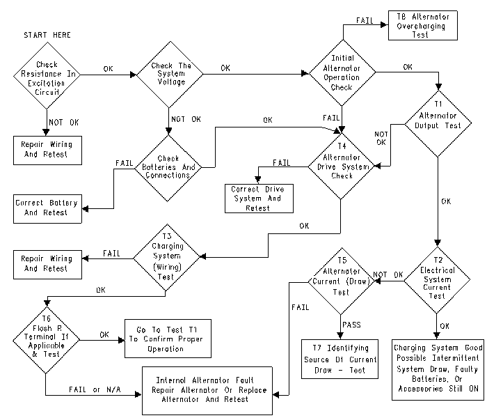 |
T1 Alternator Output - Test
SMCS - 1405-081
- Ensure that the batteries are NOT fully charged.
- Fully charged batteries have open circuit voltage above 12.5 V on 12 V systems or 25 V on 24 V systems.
- If the batteries are fully charged, then crank the engine for 30 seconds. This action reduces the battery voltage. Operate the lights for 10 minutes while the engine is off as an alternative.
- Connect the 9U-5795 Current Probe to a DMM (digital multimeter) or use a 225-8266 Ammeter Tool Gp . The multimeter must have a peak hold feature. Clamp the probe around alternator output wire "B+". Before you clamp the probe around the wire, ensure that the probe is "zeroed" .
- Set the digital multimeter to "peak hold" or "max mode" on the "mV" scale.
- Turn on all electrical accessories: lights, air conditioning and radio.
- Start the machine, and immediately set the throttle to at least 75%. The peak current will appear on the voltmeter in "peak hold" or "max" mode.
Expected Result: This current reading should be at least 90% of the specified peak output.
Results:
- OK - The current is at least 90%. For 85 amp alternators, the current should be over 76 A. For 75 amp alternators, the current should be over 67 A. For 50 amp alternators, the current should be over 45 A. Go to Testing and Adjusting, "T2 Electrical System Current - Test".
- NOT OK - The current is less than 90%. Go to Testing and Adjusting, "T4 Alternator Drive System - Check".
- OK - The current is at least 90%. For 85 amp alternators, the current should be over 76 A. For 75 amp alternators, the current should be over 67 A. For 50 amp alternators, the current should be over 45 A. Go to Testing and Adjusting, "T2 Electrical System Current - Test".
T2 Electrical System Current - Test
SMCS - 1405-081
T2a - Undesired Electrical System Current - Test (For Machines Equipped With a Main Disconnect Switch)
- Turn off all of the accessories. Turn the keyswitch to the OFF position.
- Clamp a 9U-5795 Current Probe or 225-8266 Ammeter Tool Gp around the main ground cable. Clamp the tool with the positive side away from the battery. Reset the probe (zero) before you clamp the probe around the wire. Read the current.
Expected Result: The current is below 2 A.
Results:
- YES - The current is below 2 A. Continue to Step 3.
- NO - The current is above 2 A. There is a current draw in the system. Go to Testing and Adjusting, "T5 Alternator Current - Test"
- YES - The current is below 2 A. Continue to Step 3.
- Turn the disconnect switch to the ON position. Connect a multimeter across the disconnect switch terminals. Connect the red lead to the terminal on the frame side. Connect the black lead to the terminal on the battery side. Use the 10A connections in order to avoid damage.
- Turn off the disconnect switch and read the current.
Expected Result: The current is below .050 amperes (50 mA).
Note: The standard acceptable current draw is 50 mA. A current draw above 50 mA usually indicates a problem. However, some large machines with multiple electronic control modules have a higher acceptable limit. Contact a Caterpillar dealer for more information.
Results:
- YES - The current is below 0.050 A. The charging system is currently good. The fault is possibly an intermittent draw in the system. The batteries may be faulty. Check that NO accessories were ON during the test.
- NO - The current is above 0.050 A. There is a draw in the system. Go to Testing and Adjusting, "T5 Alternator Current - Test".
- YES - The current is below 0.050 A. The charging system is currently good. The fault is possibly an intermittent draw in the system. The batteries may be faulty. Check that NO accessories were ON during the test.
T2b - Undesired Electrical System Current - Test (For Any Machine)
- Turn off all accessories. Turn the keyswitch to the OFF position.
- Clamp a 9U-5795 Current Probe or 225-8266 Ammeter Tool Gp around the main ground cable. Clamp the tool with the positive side away from the battery. Reset the probe (zero) before you clamp the probe around the wire. Read the current.
Expected Result: The current is below 2 A.
Results:
- YES - The current is below 2 A. Continue to Step 3.
- NO - The current is above 2 A. There is a current draw in the system. Go to Testing and Adjusting, "T5 Alternator Current - Test"
- YES - The current is below 2 A. Continue to Step 3.
- Remove the ground cable from the battery terminal. For systems with 4 batteries, or 12 V systems with 2 batteries, disconnect the ground cables from both negative batteries.
- Connect a multimeter between the disconnected battery ground cable and one of the negative battery terminals. Connect the red positive lead of the multimeter to the cable. The negative lead should be connected to the battery terminal. Use the 10 A connections in order to avoid damage.
Expected Result: The current is below .050 amperes (50 mA).
Note: The standard acceptable current draw is 50 mA. A current draw above 50 mA usually indicates a problem. However, some large machines with multiple electronic control modules have a higher acceptable limit. Contact a Caterpillar dealer for more information.
Results:
- YES - The current is below 0.050 A. The charging system is currently good. The fault is possibly an intermittent draw in the system. The batteries may be faulty. Check that NO accessories were ON during the test.
- NO - The current is above 0.050 A. There is a draw in the system. Go to Testing and Adjusting, "T5 Alternator Current - Test".
- YES - The current is below 0.050 A. The charging system is currently good. The fault is possibly an intermittent draw in the system. The batteries may be faulty. Check that NO accessories were ON during the test.
T3 Charging System - Test
SMCS - 1405-081
- Verify that the alternator "B+" terminal nut is tight and verify that the wire has a good connection to the "B+" terminal.
- Many Caterpillar machines are equipped with a connector for the 6V-2150 Starting/Charging Analyzer. Use of this tester replaces the testing below.
- Start the engine and set the throttle to at least 75 percent. Turn ON all electrical accessories for all test steps below. Allow the engine to run for at least 3 minutes before continuing to Step 4. The following table will assist in making calculations during this test.
Table 1 Test Step Voltage Reading Voltage should be below this for 12 volt system Voltage should be below this for 24 volt system 4 5 4 minus 5 1.0 volt 2.0 volts 6 7 6 minus 7 0.5 volt 1.0 volt 8 0.5 volt 1.0 volt
- Measure the voltage between the alternator "B+" terminal and the alternator case ground.
- Measure the voltage across the battery. Put the red lead on the + battery terminal, and put the black lead on the negative battery terminal. Step 5 should be completed as quickly as possible after Step 4.
Expected Result: On a 12 volt system, the voltage should not be greater than the voltage that was recorded in Step 4. The voltage must also be within one volt. On 24 volt systems, the voltage is within 2 volts.
Results:
- YES - If the voltage in Step 4 is not more than 1 volt for 12 volt systems (2 volts for 24 volt systems) higher than the voltage in Step 5, this test is complete and the related wiring is correct at this time. Replace the alternator or go to Testing and Adjusting, "Component - Test" in order to test the internal parts of the alternator.
- NO - If the voltage in Step 4 is more than 1 volt for 12 volt systems (2 volts for 24 volt systems) higher than the voltage in Step 5, there is high circuit resistance: corrosion, loose connections and damaged wiring. Continue to Step 6.
- YES - If the voltage in Step 4 is not more than 1 volt for 12 volt systems (2 volts for 24 volt systems) higher than the voltage in Step 5, this test is complete and the related wiring is correct at this time. Replace the alternator or go to Testing and Adjusting, "Component - Test" in order to test the internal parts of the alternator.
- Check the voltage between the machine frame and the alternator "B+" terminal. Record the voltage.
- Check the voltage between the machine frame and the + battery post. Step 7 should be completed as quickly as possible after Step 6.
Expected Result: The voltage difference between Step 6 and Step 7 does not exceed 1 volt on 24 volt systems or 0.5 volts on 12 volt systems.
Results:
- YES - The voltage difference does not exceed the tolerance. The charging circuit is good. Go to Step 8.
- NO - The voltage difference exceeds the tolerance. There is high resistance in the charging circuit: loose cables, corroded cables, damaged cables, faulty circuit breaker and faulty main relay. Correct the problem and retest the system.
- YES - The voltage difference does not exceed the tolerance. The charging circuit is good. Go to Step 8.
- Check the voltage between the negative battery post and the alternator case ground.
Expected Result: The voltage does not exceed 1 volt on 24 volt systems or 0.5 volts on 12 volt systems.
Results:
- YES - The voltage difference does not exceed the tolerance. The ground circuit is good. There is an internal problem with the alternator. Replace the alternator or go to Testing and Adjusting, "Component - Test" in order to test the internal parts of the alternator.
- NO - The voltage difference exceeds the tolerance. There is high resistance in the ground circuit: loose cables, corroded cables, loose alternator mounting and poor engine ground. Correct the problem and retest the system.
- YES - The voltage difference does not exceed the tolerance. The ground circuit is good. There is an internal problem with the alternator. Replace the alternator or go to Testing and Adjusting, "Component - Test" in order to test the internal parts of the alternator.
T4 Alternator Drive System - Check
SMCS - 1405-081
- Check the condition of the alternator drive belt. If the drive belt is oily, clean the pulleys. Replace the drive belt, and retest the system. If the drive belt is wet, dry the belt and retest the system. If the drive belt is worn, replace the belt and retest the system.
- Check the tension of the alternator drive belt. If the tension is off, adjust the tension.
- Check the nut on the alternator pulley. If the nut is loose, tighten the nut and retest the system.
- If all of the previous steps find no problems go to Testing and Adjusting, "T3 Charging System - Test".
T5 Alternator Current - Test
SMCS - 1405-081
- Turn the keyswitch to the OFF position.
- Connect the 9U-5795 Current Probe to a DMM (digital multimeter) or use a 225-8266 Ammeter Tool Gp . Clamp the probe around the alternator output wire ("B+"). Before you clamp the probe around the wire, ensure that the probe is "zeroed" .
- Read the current.
Expected Result: The current is under 2 A.
Results:
- YES - The current is under 2 A. Continue to Step 4.
- NO - The current is over 2 A. There is an internal problem with the alternator. Replace the alternator or go to Testing and Adjusting, "Component - Test".
- YES - The current is under 2 A. Continue to Step 4.
- Disconnect the B+ terminal wire from the alternator. Connect the red lead of the multimeter to the wire that was disconnected. Connect the black lead of the multimeter to the alternators B+ terminal. Set the multimeter on the 10 amp scale. Read the current.
Expected Result: The current is under 0.015 A.
Results:
- YES - The current is under 0.015 A. The alternator is operating correctly. There is a current draw on the machine. Go to Testing and Adjusting, "T7 Identifying Source Of Current Draw - Test".
- NO - The current is over 0.015 A. There is an internal problem with the alternator. Replace the alternator or go to Testing and Adjusting, "Component - Test".
- YES - The current is under 0.015 A. The alternator is operating correctly. There is a current draw on the machine. Go to Testing and Adjusting, "T7 Identifying Source Of Current Draw - Test".
T6 Residual Magnetism Restoration
SMCS - 1405-081
Reference: Service Magazine, SEBD1672 July 1986, "Brushless Alternators May Not Charge In Certain Conditions"
- Start the engine and set the throttle to at least 75%.
- Connect a voltmeter between the "B+" terminal and the alternator case ground.
- If a wire is connected, disconnect the wire from the "R" terminal.
Expected Result: The voltage does not change.
Results:
- YES - The voltage stays the same. Continue to Step 4.
- NO - The voltage rises and the alternator begins charging. The wire to the "R" terminal is shorted. Repair the wiring or replace the wiring. Go to Troubleshooting, "Initial Troubleshooting Procedure" and retest the system.
- YES - The voltage stays the same. Continue to Step 4.
- Connect one end of a jumper wire to the "B+" terminal of the alternator.
- Connect the other end of the jumper wire to the "R" terminal of the alternator for two seconds.
Expected Result: The voltage output rises on the "B+" terminal.
Results:
- YES - The voltage output rises. The alternator is now charging. Go to Troubleshooting, "Initial Troubleshooting Procedure" and retest the system.
- NO - The voltage output does not rise. Repair the alternator or replace the alternator.
- YES - The voltage output rises. The alternator is now charging. Go to Troubleshooting, "Initial Troubleshooting Procedure" and retest the system.
T7 Identifying Source of Current Draw - Test
SMCS - 1405-081
- Make sure that every electrical component is turned OFF. Make sure that the keyswitch is turned OFF. Make sure that the dome lights are OFF.
- Clamp a 9U-5795 Current Probe or 225-8266 Ammeter Tool Gp around the main ground cable. Clamp the tool with the positive side away from the battery. Reset the probe (zero) before clamping the probe around the wire. Use the current probe if the draw is above approximately 2 A. Use the Ammeter if the draw is below approximately 2 A.
- Monitor the current and remove fuses and breakers one at a time. Check the current after each fuse (breaker) is removed. After removing a fuse (breaker) and observing the current, reinstall the fuse (breaker). Start with the main fuses (circuit breakers) first, and proceed to smaller circuits.
- If a removal of a fuse causes the current to drop, then the problem is in that circuit.
- Check if any components on the circuit are ON.
- If everything is OFF, disconnect electrical components on that circuit one at a time and monitor current.
- After all of the components in that circuit have been disconnected, check the current. If the problem still exists, then check the wiring for corrosion or shorts to ground.
Note: The standard acceptable current draw is 50 mA. A current draw above 50 mA usually indicates a problem. However, some large machines with multiple electronic control modules have a higher acceptable limit. Contact a Caterpillar dealer for more information.
T8 Alternator Overcharging - Test
SMCS - 1405-081
- Verify that the nut for the "B+" terminal is tight. Verify that the wire has a good connection to the "B+" terminal.
- Many Caterpillar machines are equipped with a connector for the 6V-2150 Starting/Charging Analyzer. See Systems Operation, SENR2947, "Starting and Charging Systems". Use of this analyzer replaces the testing that is listed below. If the analyzer finds a problem, correct the problem and retest the system. Go to Troubleshooting, "Initial Troubleshooting Procedure".
- Run the engine at 75 percent. Turn ON all electrical accessories for all test steps below. Allow the engine to run for at least 3 minutes before you continue to 4. The following table will assist in making calculations during the test.
Table 1 Test Step Voltage Reading Voltage should be below this for 12 volt system Voltage should be below this for 24 volt system 4 5 4 minus 5 1.0 volt 2.0 volts 6 7 6 minus 7 0.5 volt 1.0 volt
- Measure the voltage between the "B+" terminal and ground.
- Measure the voltage across the battery. Put the red lead on the + battery terminal, and put the black lead on the negative battery terminal. Step 5 should be completed as quickly as possible after Step 4.
Expected Result: On 12 volt systems, the voltage is within one volt of the voltage that was recorded in Step 4. On 24 volt systems, the voltage is within 2 volts.
Results:
- YES - If the voltage in Step 4 is not more than 1 volt for 12 volt systems (2 volts for 24 volt systems) higher than the voltage in Step 5, this step is complete and the related wiring is correct at this time. There is an internal malfunction in the alternator. Refer to Testing and Adjusting, "Component - Test".
- NO - If the voltage in Step 4 is more than 1 volt for 12 volt systems (2 volts for 24 volt systems) higher than the voltage in Step 5, there is high circuit resistance: corrosion, loose connections and damaged wiring. Go to Step 7.
- YES - If the voltage in Step 4 is not more than 1 volt for 12 volt systems (2 volts for 24 volt systems) higher than the voltage in Step 5, this step is complete and the related wiring is correct at this time. There is an internal malfunction in the alternator. Refer to Testing and Adjusting, "Component - Test".
- Check the voltage between the machine's frame and the "B+" terminal. Record the voltage.
- Check the voltage between the machine frame and the + battery post. Step 7 should be completed as quickly as possible after Step 6.
Expected Result: The voltage difference between Step 6 and Step 7 does not exceed 1 volt on 24 volt systems or 0.5 volts on 12 volt systems.
Results:
- YES - The voltage difference does not exceed the tolerance. The charging circuit is good. There is an internal malfunction in the alternator. Refer to Testing and Adjusting, "Component - Test".
- NO - The voltage difference exceeds the tolerance. There is high resistance in the charging circuit: loose cables, corroded cables, damaged cables, faulty circuit breaker and faulty main relay. Correct the problem. Go to Troubleshooting, "Initial Troubleshooting Procedure" and retest the system.
- YES - The voltage difference does not exceed the tolerance. The charging circuit is good. There is an internal malfunction in the alternator. Refer to Testing and Adjusting, "Component - Test".
Component - Test
SMCS - 1405-081
Stator
Check the resistance that is between each of the phases. Measure the resistance between the end of each lead wire and neutral point. The resistance should be less than 1 ohm.
Measure the insulation resistance between the core and the coil. Use the 142-5055 Insulation Tester Group. Set the insulation tester at 500V. The resistance should be more than 100000 ohms. When there is no continuity, check the lead wire connection. Disconnection of the stator coil is unlikely.
Rectifier Diodes
 |
|
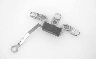
| Illustration 1 | g00654958 |
Use the "Check Diode" function of the multimeter.
- Place one of the meter leads on regulator strap (1) .
- Connect the other meter lead to each of the rectifier bridge straps (2) .
- Record the meter readings.
- Reverse the meter leads.
- Place the meter lead that was connected to the rectifier bridge strap during 8 on regulator strap (1) .
- Connect the other meter lead to each of the rectifier bridge straps (2) .
- Record the meter readings.
The diode is functioning properly when the leads are connected one way and the multimeter shows "0L". Then, the multimeter shows approximately .5 volts when the lead connections are reversed.
The diode is shorted when the leads are connected one way and the multimeter shows "00". Then, the multimeter shows "00" when the lead connections are reversed.
The diode is open when the leads are connected one way and the multimeter shows "0L". Then, the multimeter shows "0L" when the lead connections are reversed.
Regulator
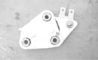
The test for the regulator does not cover all of the possible failures. The test verifies a few common problems.
 |
|
| Illustration 2 | g00628079 |
The regulator controls the output of the alternator. The regulator limits the alternator voltage to a preset value by controlling the field current. The regulator operates electronically in order to turn on the voltage across the field winding. The regulator then switches off the voltage. The switching can occur at a low rate such as 10 times in one second. The switching can occur at a high rate such as several thousand times in one second.
The voltage should not vary more than 0.3 volts during the procedure. The test measures the voltage when the regulator changes the state of the field current. This test will determine problems in the following components: Diode Trio, Field Coil and Regulator.
 |
|
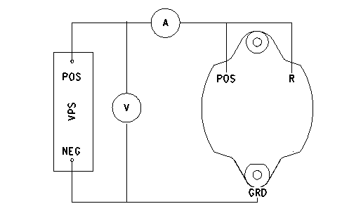
| Illustration 3 | g00649573 |
- Connect a variable power supply and two multimeters to the alternator. The setup is shown in illustration 3.
- Adjust the variable power supply until multimeter (A) indicates a current draw.
- Measure the voltage. This voltage is the "Turn On" voltage. Record your results.
When the alternator is operating correctly, the voltage is 14.0 ±0.3 volts for a 12 volt system and 27.4 ±0.6 volts for a 24 volt system. If the voltage is out of specifications, replace the regulator.
- Multimeter (A) reads the field current. When the alternator is operating correctly, the field current is 5.7 to 7.1 amperes for a 12 volt system and 2.5 to 3.8 amperes for a 24 volt system.
If the amperage is high, the field coil is shorted. If the amperage is 0, the following conditions may exist:
- The field coil is open.
- The brushes are open.
- The regulator is open.
- The field coil is open.
- Divide the voltage from 3 by the field coil resistance. Refer to Specifications, "Alternator" for the field coil resistance of your alternator.
- Adjust the variable power supply to the "Turn On" voltage. The "Turn On" voltage was measured in 2.
- Adjust the voltage until multimeter (A) reads 0 amperes. Record your results. This is the "Turn Off" voltage.
- Subtract the "Turn On" voltage from the "Turn Off" voltage. The difference should not be greater than 0.3 volts. A difference that is larger than 0.3 volts indicates a regulator malfunction.
30SI Series and 34SI Series Alternator - SENR7508
Información general (Sistema de control electrónico)
SMCS - 1901
Varios sensores suministran información acerca de la máquina y del motor al Módulo de Control Electrónico (ECM). El ECM procesa la información recibida. El ECM envía señales electrónicas a los solenoides de los inyectores de combustible. Los solenoides son energizados para comenzar la descarga de combustible de las bombas de inyección de combustible. Los solenoides son de-energizados para interrumpir la descarga de combustible de las bombas de inyección de combustible. Vea una explicación completa del proceso de inyección de combustible en Operación de Sistemas, "Inyector de combustible".
Parámetros del sistema monitor
SMCS - 1901
El Módulo de control electrónico (ECM) del motor vigila los parámetros de operación del motor. Si un parámetro de operación del motor excede una gama aceptable, el ECM iniciará una acción. Tres posibles acciones del ECM pueden estar disponibles: "ADVERTENCIA", "REDUCCIÓN DE POTENCIA" y "PARADA". Use el Técnico Electrónico (ET) de Caterpillar para determinar las opciones implícitas reales y la configuración específica para su aplicación. Vea información específica sobre los parámetros del sistema monitor en el manual Localización y solución de problemas.
Se habilita el sistema monitor del motor después de que arranque el motor. Cuando la velocidad (rpm) del motor excede un punto que está 50 rpm por debajo de la velocidad baja en vacío, el ECM comprueba los niveles de los parámetros. El ECM comprueba los niveles de los parámetros para determinar si dichos niveles exceden los puntos de ajuste del sistema monitor.
Cualquier acción del sistema monitor registrará un suceso. Si se ha activado la vigilancia para ese parámetro, el suceso se mostrará en la pantalla de estado del Técnico Electrónico Caterpillar (ET Cat). Si se desactiva la vigilancia para ese parámetro, no se mostrará un suceso en el ET Cat.
Cualquier avería de un sensor causará la desactivación de la porción correspondiente del sistema monitor. Habrá un código de diagnóstico activo para el sensor averiado pero no se registra un suceso. Vea información adicional sobre sensores en Localización y solución de problemas.
Comprobación y calibración de la sincronización de la inyección electrónica usando la herramienta de servicio electrónica
SMCS - 1901
Vea el procedimiento apropiado para calibrar la sincronización electrónica de la inyección en Localización y solución de problemas.
Indicadores de presión del aceite del motor
SMCS - 7485
Un indicador de presión del aceite defectuoso o un emisor defectuoso pueden indicar una condición de baja presión del aceite o de alta presión del aceite.
El 1U-5470 Grupo de Presión del Motor puede usarse para comparar los indicadores en el panel de instrumentos con la presión del aceite que se muestra en el Técnico Electrónico Cat® (ET, Electronic Technician).
Sensor de temperatura del refrigerante - Probar
SMCS - 7453-081
 |
|
El fluido que escapa a presión puede causar lesiones personales. Si el medidor indica que hay presión, presione la válvula de alivio para aliviar la presión antes de quitar una manguera del radiador. |
Introducción
Utilice este procedimiento para revisar el sensor de temperatura del refrigerante.
Herramientas necesarias
| Herramientas necesarias | ||
|---|---|---|
| Número de pieza | Nombre de la pieza | Cant. |
| 2F-7112 | Termómetro | 1 |
| 6B-5072 | Buje de Reducción | 1 |
Preparación de la prueba
 |
|
| Ilustración 1 | g00769081 |
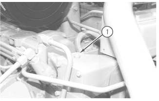
| Ubicación de la prueba (1) Tapón |
|
- Apague el motor.
- Deje que el motor se enfríe.
- Quite el tapón (1).
- Instale el 6B-5072 Buje de Reducción y el 2F-7112 Termómetro.
- Conecte el Técnico Electrónico (ET, Electronic Technician) Cat® al conector de la herramienta de servicio.
Procedimiento de prueba
Nota: Asegúrese de que el nivel de refrigerante esté en el nivel adecuado antes de efectuar esta prueba.
- Inicie el Cat ET.
- Arranque el motor y déjelo funcionar hasta que la temperatura alcance la gama deseada, según el termómetro de prueba.
- Controle la temperatura del refrigerante en el Cat ET. Controle la temperatura del refrigerante en el termómetro de prueba.
- Compare la temperatura del refrigerante en el Cat ET con la temperatura del refrigerante en el termómetro de prueba. Si las dos mediciones son aproximadamente iguales, el sensor está en buenas condiciones. Si las dos mediciones no son aproximadamente iguales, es posible que haya un problema en el sensor. Instale un sensor nuevo y verifique que se haya solucionado el problema.
Herramientas de prueba del sistema eléctrico
SMCS - 0785
Referencias
Referencia: Pruebas y ajustes de los componentes eléctricos, REG00636 para conocer las especificaciones y los procedimientos de pruebas completos de los componentes del circuito de arranque y del circuito de carga.
Referencia: Manual de Operación, NEHS0764 para obtener información completa sobre el uso del 177-2330 Analizador de Baterías.
Referencia: Manual de Operación, NEHS0973 para obtener información completa sobre el uso del 271-8590 Grupo de Analizador de Arranque/Carga.
Introducción
La mayoría de las pruebas del sistema eléctrico se pueden realizar en el motor. En primer lugar, revise que el material aislante de los cables esté en buenas condiciones. Asegúrese de que las conexiones de cables estén limpias y ajustadas. Revise que la batería esté completamente cargada. Si la prueba de motor indica que un componente no funciona correctamente, quite el componente del motor para realizar más pruebas.
177-2330 Analizador de baterías
 |
|
| Ilustración 1 | g03717970 |
| 177-2330 Analizador de baterías | |
El 177-2330 Analizador de Baterías prueba rápidamente cualquier batería de 6 V o 12 V con una capacidad de 50 a 4.000 amperios para arranque en frío (CCA, Cold Cranking Amp), 65 a 5.000 amperios para arranque (CA, Crancking Amp) o 6 a 500 amperios por hora (A-Hr, Amp Hour).
La prueba se puede completar en solo 20 segundos y determina si la batería está en buenas condiciones.
El 177-2330 Analizador de Baterías presenta lo siguiente:
- De manera rápida y precisa, pruebe la condición de las baterías de 6 V y 12 V (incluso descargadas hasta un mínimo de un voltio). Verifica el estado total de carga, la condición y el voltaje de batería.
- Las baterías se pueden probar en la máquina o en el vehículo. La batería no necesita estar cargada por completo en el momento de la prueba.
- Se ahorra tiempo y dinero, lo que permite que los distribuidores prueben la condición de una batería mientras el cliente está presente (es muy conveniente para reclamos de garantía).
- Elimina la necesidad de cargar y descargar una batería para comprobar su estado.
- Compensa las temperaturas frías al probar las baterías en condiciones extremas.
- La característica de desenergizado prolonga la vida útil de la batería en el analizador.
271-8590 Grupo analizador de arranque/carga
 |
|
| Ilustración 2 | g01789234 |
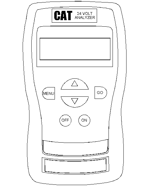
271-8590 Grupo analizador de arranque/carga
El 271-8590 Grupo de Analizador de Arranque/Carga es una herramienta portátil y manual que se utiliza para probar las condiciones de todas las baterías de 6 V, 8 V y 12 V, así como de los conjuntos de baterías de 6 V, 8 V, 12 V y 24 V. El probador también puede utilizarse para probar los sistemas de arranque y de carga. El analizador cuenta con un dispositivo de entrada multifuncional que se utiliza con las sondas de multímetro que son de compra optativa. El analizador también cuenta con una función de impresión que se utiliza con una impresora que es de compra optativa.
225-8266 Grupo de amperímetro
 |
|
| Ilustración 3 | g01012117 |
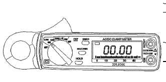
| 225-8266 Grupo de amperímetro | |
El 225-8266 Grupo de Amperímetro es un instrumento portátil y autocontenido que permite que las mediciones de corriente eléctrica se efectúen sin interrumpir el circuito o sin alterar el material aislante de un conductor. Hay una pantalla digital en el amperímetro que muestra las mediciones de corriente en una gama de 1 A a 1.200 A. Se puede conectar un 6V-6014 Cable entre el amperímetro y un multímetro digital para medir una corriente menor que 1 A.
Se usa una palanca para abrir una mordaza en el medidor que se sujeta a cualquier conductor que tenga hasta 23 mm (0.90 inch) de diámetro. La mordaza del medidor se cierra alrededor del conductor para medir la corriente. Se utiliza un selector para ajustar la gama apropiada de la lectura de amperaje. Un botón "HOLD" (detener) en el medidor permite mostrar la última lectura en la pantalla de manera prolongada. Si la medición se efectúa en un área de acceso restringido, el medidor conserva los datos de medición que figuran en la pantalla hasta que el usuario los borra. Se usan baterías para impulsar el amperímetro.
Nota: Para obtener información completa sobre el uso del amperímetro, consulte la Guía del usuario del amperímetro. Esta guía se envía con la unidad.
146-4080 Grupo de Multímetro Digital o 257-9140 Multímetro Digital
 |
|
| Ilustración 4 | g01015638 |
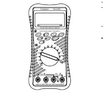
| 146-4080 Grupo de multímetro digital | |
El 146-4080 Grupo de Multímetro Digital es un instrumento portátil que tiene una pantalla digital. El multímetro tiene un templado superficial con una tapa protectora de caucho que brinda protección adicional contra daños en aplicaciones de campo. El 146-4080 Grupo de Multímetro Digital puede usarse para efectuar las siguientes mediciones:
- Amperaje
- Capacitancia
- Frequency (Frecuencia)
- Modulación de duración de impulsos (PWM, pulse width modulation)
- Resistencia
- Temperatura
- Voltaje
El multímetro tiene un indicador de ohmios instantáneo que permite revisar la continuidad para hacer una inspección rápida de los circuitos. Se pueden efectuar mediciones de temperatura utilizando el adaptador para termopares de tipo K. Se puede utilizar un Adaptador de Interfaz RS-232 para que funcione en conjunto con otras pantallas y herramientas electrónicas.
Nota: Para obtener información completa sobre el uso del multímetro, consulte el Manual del Operador del multímetro. Este manual se envía con la unidad.
Batería
SMCS - 1401-081
 |
|
No desconecte nunca de la batería ningún circuito unitario de carga o cable del circuito de la batería cuando se opere la unidad de carga. De producirse una llama se puede provocar una explosión debido a la mezcla inflamable de vapor de hidrógeno y oxígeno desprendida del el electrólito por las salidas de la batería. Como consecuencia se pueden producir lesiones personales. |
El circuito de la batería es una carga eléctrica en la unidad de carga. La carga es variable debido al estado de la carga de la batería.
| ATENCION |
|---|
|
La unidad de carga se dañará si las conexiones entre la batería y la unidad de carga se rompen mientras está en operación. Pueden producirse daños debido a que la carga de la batería se pierde y porque hay un aumento en el voltaje de carga. El alto voltaje dañará la unidad de carga, el regulador y otros componentes eléctricos. |
Use el Probador de Carga de Baterías 4C-4911 para probar baterías que no mantengan la carga cuando estén activas. Consulte el Manual de Operación, SEHS9249 para obtener instrucciones detalladas sobre el uso del Probador de Carga de Baterías 4C-4911. Vea en la Instrucción Especial, SEHS7633 el procedimiento correcto y las especificaciones que deben usarse al probar las baterías.
Sistema de carga
SMCS - 1406-081
La condición de carga de la batería en cada inspección regular muestra si el sistema de carga opera correctamente. Es necesario un ajuste cuando la batería está constantemente en una condición de carga baja o se necesita una gran cantidad de agua. Una gran cantidad de agua sería más de una onza de agua por celda, ya sea por semana o por cada 100 horas de servicio.
Cuando sea posible, efectúe una prueba de la unidad de carga y del regulador de voltaje del motor, y utilice los cables y los componentes que forman parte permanente del sistema. Las pruebas en banco del motor darán una prueba de la unidad de carga y del funcionamiento del regulador de voltaje. Esta prueba dará una indicación de las reparaciones que se necesiten. Después de realizadas las reparaciones, efectúe una prueba para comprobar que las unidades se han reparado según las condiciones originales de funcionamiento.
Consulte la Instrucción Especial, REHS0354, "Localización y solución de problemas del sistema de carga" para obtener información sobre los procedimientos correctos a fin de probar el sistema de carga. Esta publicación contiene también las especificaciones que debe implementar cuando pruebe el sistema de carga.
Para comprobar la salida correcta del alternador, vea el módulo de Especificaciones.
Antes de empezar las pruebas en el motor, se debe comprobar el sistema de carga y la batería de acuerdo con los pasos siguientes.
- La batería debe estar cargada al menos un 75 por ciento (peso específico de 1,225) con respecto a la carga completa. La batería debe estar bien sujeta. El retén no debe ejercer un esfuerzo demasiado grande sobre la batería.
- Los cables entre la batería, el motor de arranque y la conexión a tierra del motor deben ser del tamaño correcto. Los alambres y los cables no deben tener corrosión. Los alambres y los cables deben tener abrazaderas de soporte de cables para evitar esfuerzos en las conexiones de baterías (terminales).
- Los cables, empalmes, interruptores e instrumentos del tablero que tengan una relación directa con el circuito de carga deben proporcionar un control adecuado del circuito.
- Inspeccione los componentes de accionamiento de la unidad de carga para asegurarse de que no tengan grasa ni aceite. Asegúrese de que los componentes de accionamiento puedan operar la unidad de carga.
Regulador del alternador
SMCS - 1405-081
La velocidad de carga del alternador debe comprobarse cuando el alternador está cargando demasiado la batería. La velocidad de carga del alternador debe comprobarse cuando el alternador no esté cargando suficiente la batería. Consulte en el módulo de Especificaciones todas las especificaciones de pruebas para los alternadores y reguladores.
No se puede efectuar un ajuste para cambiar el régimen de carga de los reguladores del alternador. Si el régimen de carga no es correcto, es necesario reemplazar el regulador.
Ajuste de la tuerca de la polea del alternador

Apriete la tuerca que sujeta la polea con las herramientas mostradas. Consulte el módulo de Especificaciones para obtener el par.
Sistema de arranque eléctrico
SMCS - 1450-081
Use el multímetro en la gama de VCC para localizar los componentes del sistema de arranque que no funcionen.
Mueva el interruptor de control de arranque para activar los solenoides de arranque. Se puede oír la operación del solenoide de arranque a medida que los piñones de los motores de arranque engranan con la corona en el volante del motor.
Si no funciona un solenoide de un motor de arranque, es posible que la corriente de la batería no haya alcanzado el solenoide. Conecte un conductor del multímetro a la conexión (terminal) para el cable de batería en el solenoide. Conecte el otro conductor a una conexión a tierra en buenas condiciones. Una lectura igual a cero indica que hay un circuito interrumpido procedente de la batería. Es necesario efectuar más pruebas cuando existe una lectura de voltaje en el multímetro.
La operación del solenoide también cierra el circuito eléctrico del motor. Conecte un conductor del multímetro a la conexión (terminal) del solenoide conectado al motor. Ajuste el otro conductor a una buena conexión a tierra. Active el solenoide de arranque y observe en el multímetro. Una lectura del voltaje de batería indica que el problema está en el motor. Se debe quitar el motor para efectuar pruebas adicionales. Una lectura de cero en el multímetro indica que los contactos del solenoide no se cierran. Repare el solenoide si los contactos no se cierran. Tal vez sea necesario ajustar el espacio libre del engranaje de piñón del motor de arranque.
Efectúe una prueba. Conecte un conductor del multímetro a la conexión (terminal) para el cable pequeño al solenoide y conecte el otro conductor a tierra. Observe el multímetro y active el solenoide de arranque. Una lectura de voltaje indica que el problema está en el solenoide. Una lectura de cero indica que el problema está en el interruptor de arranque o en los cables del interruptor de arranque.
Conecte un conductor del multímetro al interruptor de arranque en la conexión (terminal) para el cable de la batería. Ajuste el otro conductor a una buena conexión a tierra. Una lectura igual a cero indica que hay un circuito interrumpido procedente de la batería. Revise el disyuntor y los cables. Si hay una lectura de voltaje, el problema está en el interruptor de arranque o en los cables de este interruptor.
Los motores de arranque que operan con demasiada lentitud pueden tener una sobrecarga debido a una fricción excesiva en el motor que se arranca. La operación lenta de los motores de arranque puede deberse también a las condiciones siguientes:
- Cortocircuito
- Conexiones flojas
- Suciedad en los motores
El problema con el sistema de arranque pudo ser causado por la batería o por problemas del sistema de carga. Si se sospecha que hay problemas en el sistema de arranque, consulte el Manual de Servicio, SENR3581, "Motores de Arranque de las Series 37-MT, 41-MT y 42-MT". Esta publicación contiene la localización y solución de problemas para el sistema de arranque, los procedimientos de prueba y las especificaciones.
Ajuste de la holgura del piñón
SMCS - 1454-025
Cuando se instale el solenoide, ajuste el espacio libre del piñón. El ajuste puede efectuarse con el motor de arranque quitado.
 |
|
| Ilustración 1 | g01192756 |
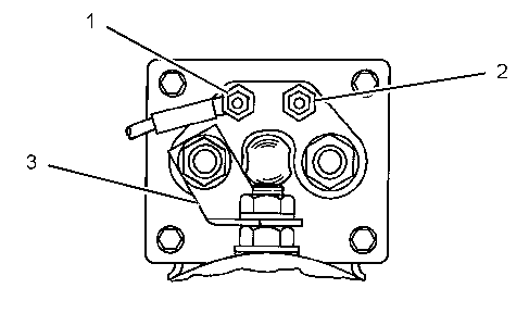
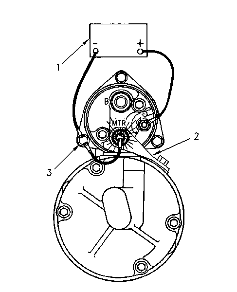
| Conexión para comprobar el espacio libre del piñón (1) Terminal de conexión a tierra (2) Terminal de interruptor (3) Conector |
|
- Instale el solenoide sin el conector (3) desde los terminales del MOTOR en el solenoide al motor.
- Conecte una batería, que tenga el mismo voltaje que el solenoide, al terminal "SW" (2).
- Conecte el otro lado de la batería al conector (3).
- Conecte por un momento un cable del terminal del solenoide, marcado "MOTOR", al terminal de conexión a tierra. El piñón se desplazará a la posición de arranque y permanecerá en dicha posición hasta que se desconecte la batería.
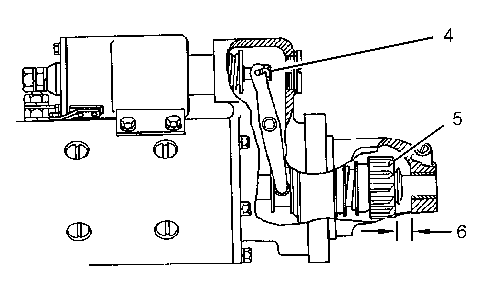
Ilustración 2 g01192757 Ajuste del espacio libre del piñón
(4) Tuerca del eje
(5) Piñón
(6) Espacio libre del piñón - Empuje el piñón hacia el extremo con el conmutador para eliminar el movimiento libre.
- El espacio libre del piñón (6) debe ser de 9,1 mm (0,36 pulg).
- Para ajustar el espacio libre del piñón, quite el tapón y haga girar la tuerca del eje (4).
37-MT, 41-MT, and 42-MT Series Starting Motors - SENR3581
No Load - Test
SMCS - 1453-081
| Tools Needed | |
|---|---|
| 6V-7070 | Digital Multimeter |
| 225-8266 | Ammeter Tool Gp |
| 1U-6602 | Photo-Tachometer |
The following procedure is used in order to perform the no-load test after the starting motor has been repaired. The test should also be performed when the starting motor is removed from the machine. In order to check a starting motor completely, the complete procedure should be followed. To check the starting motor components, refer to the Testing and Adjusting section.
|
|
|
| Illustration 1 | g02718921 |
|
No load test diagram (24V) |
|
- Illustration 1 shows a 24 V system with two 12 V batteries that are connected in series to a starting motor. Connect one 12 V battery for a 12 V system. Connect the positive side of the battery cable to the "BAT" terminal of the starting motor solenoid. Connect the negative side of the battery cable to the negative terminal of the starting motor.
- As shown, connect an open switch between the "S" terminal and the "BAT" terminal of the solenoid.
- Connect the multimeter red lead to the "Mtr" terminal on the solenoid. Connect the multimeter black lead to the negative terminal of the starting motor.
- Use a phototach or a rpm indicator in order to measure the speed of the armature.
- Close the switch. The measurements in Table 2 should be observed:
Table 2 No Load Test 37-MT
12 V37-MT
24 V41-MT
12 V41-MT
24 V42-MT
12 V42-MT
24 VMinimum Voltage 11 V 23 V 11 V 23 V 11 V 23 V Minimum Speed 5501 rpm 3215 rpm 5501 rpm 7200 rpm 5100 rpm 5960 rpm Maximum Speed 8535 rpm 4041 rpm 8535 rpm 9700 rpm 8700 rpm 9326 rpm Minimum Current Draw 100 Amp 68 Amp 100 Amp 68 Amp 100 Amp 68 Amp Maximum Current Draw 155 Amp 100 Amp 155 Amp 100 Amp 155 Amp 100 Amp
- If the voltage is below the minimum, the batteries are low and the batteries need charged.
Note: If the voltage is higher, the speed will be proportionally higher.
No Load Test Results
The following information provides some results of a no-load test and the possible problems.
- A rated current draw at a no-load speed indicates a normal starting motor.
- A low free speed and a high current draw indicate:
- An increase in friction could be caused by tight bearings, dirty bearings, or worn bearings. A bent armature or loose field pole shoes that would allow the armature to drag are possible causes of increased friction.
- A shorted armature could cause a high current draw. A shorted armature can be checked on a growler tester after disassembly.
- A grounded armature or a grounded field winding could cause a high current draw. Check for grounds after disassembly.
- Failure to operate with a high current draw indicates:
- A direct ground in the terminal or field windings.
- The bearings cease to operate properly. The bearings can be seen by turning the armature by hand.
- Failure to operate with no current draw indicates:
- An open field circuit will cause a failure. The system can be checked for an open field circuit with a multimeter after disassembly.
- An open armature will cause a failure. Inspect the commutator for badly burned bars.
- Broken brush springs, worn brushes, or high insulation between the commutator bars could prevent good contact between the brushes and the commutator.
- A low no-load speed and a low current draw indicate:
- An internal resistance that is high is possibly caused by poor connections, leads that are faulty, a commutator that is dirty, and/or causes that are listed in step 4.
- A high free speed and a high current draw indicate:
- A shorted field circuit will cause a failure. Check the field winding for shorts after disassembly.
Starting Motor Solenoid - Test
SMCS - 1453-081
Note: The graphics that are illustrated in this section refer to the solenoids that are 24 VDC. Solenoids that are 12 VDC use the same procedure, but only one battery that is 12 VDC is used.
| Required Tools | ||
|---|---|---|
| Part Number | Description | Quantity |
| 6V-7070 | Digital Multimeter | 1 |
| 225-8266 | Ammeter Tool Gp | 1 |
| 4C-4911 | Battery Load Tester | 1 |
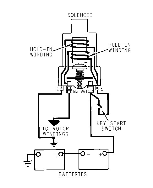 |
|
| Illustration 1 | g00713118 |
|
Basic solenoid circuit |
|
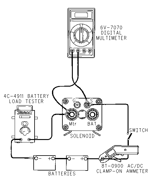
A basic four terminal starting motor solenoid circuit is shown in Illustration 1. The two windings that are found in the solenoid are the hold-in winding and the pull-in winding. The windings can be checked with the following procedures.
Hold-in Winding Test
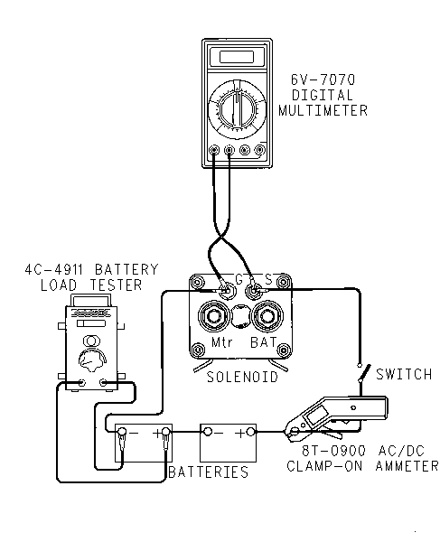 |
|
| Illustration 2 | g00713128 |
|
Hold-in winding test |
|
- Refer to Illustration 2 in order to make the connections to the solenoid. Disconnect all other leads to the solenoid.
- Close the switch. Observe the reading on the multimeter. Use the battery load tester to adjust the battery voltage until the correct voltage is obtained. Refer to Table 2.
Table 2 Voltage
SpecificationsModel Operating Voltage Measured Voltage 37-MT 12V 12V 37-MT 24V 20V 41-MT 12V 10V 41-MT 24V 20V 42-MT 12V 10V 42-MT 24V 20V
- Observe the reading on the clamp-on ammeter. Refer to Table 3 for the correct amperage.
Note: A high reading indicates a shorted winding. A low reading indicates excessive resistance.
Table 3 Current Specifications Model Operating Voltage Measured Current 37-MT 12V 23±2A 37-MT 24V 6.75A
max41-MT 12V 23.0A 41-MT 24V 14.6A 42-MT 12V 23.0A 42-MT 24V 14.6A
- The hold-in winding can also be checked by measuring the resistance. Disconnect the batteries. Select the "200 Ω" range on the multimeter. Connect one of the leads of the multimeter to the "S" terminal and connect the other lead to the "G" terminal. Refer to Table 4 for the correct resistance reading.
Table 4 Resistance Specifications Model Operating Voltage Measured Resistance 37-MT 12V .50 to .56Ω 37-MT 24V 2.96 to 3.48Ω 41-MT 12V .50 to .59Ω 41-MT 24V 1.37 to 1.77Ω 42-MT 12V .50 to .59Ω 42-MT 24V 1.37 to 1.77Ω
- Replace the solenoid if any of the above readings are incorrect.
Pull-in Winding Test
 |
|
| Illustration 3 | g00713129 |
|
Pull-in winding test |
|
- Refer to Illustration 3 in order to make the connections to the solenoid. Disconnect all other leads to the solenoid.
- Close the switch. Observe the reading on the multimeter. Use the battery load tester in order to adjust the battery voltage. Refer to Table 5 for the correct voltage.
Table 5 Voltage
SpecificationsModel Operating Voltage Measured Voltage 37-MT 12V 12V 37-MT 24V 20V 41-MT 12V 10V 41-MT 24V 20V 42-MT 12V 10V 42-MT 24V 20V
- Observe the reading on the clamp-on ammeter. Refer to Table 6 for the correct current value.
Note: A high reading indicates a shorted winding. A low reading indicates excessive resistance. To avoid excessive heat, do not leave the switch closed for more than 10 seconds at a time. The current will decrease as the heat increases.
Table 6 Current Specifications Model Operating Voltage Measured Current 37-MT 12V 36±2A 37-MT 24V 89±5A 41-MT 12V 56.5±4.5A 41-MT 24V 92.5±7.5A 42-MT 12V 56.5±4.5A 42-MT 24V 92.5±7.5A
- The pull-in winding can also be checked by measuring the resistance. Disconnect the batteries. Select the "200 Ω" range on the multimeter. Connect one of the leads of the multimeter to the "S" terminal and connect the other lead to the "Mtr" terminal. Refer to Table 7 for the correct resistance reading.
Table 7 Resistance Specifications Model Operating Voltage Measured Resistance 37-MT 12V .17 to .19Ω 37-MT 24V .64 to .70Ω 41-MT 12V .11 to .15Ω 41-MT 24V .43 to .49Ω 42-MT 12V .11 to .15Ω 42-MT 24V .43 to .49Ω
- Replace the solenoid if any of the above readings are incorrect.
Brush and Brush Holder - Check
SMCS - 1453-535
| Tools Needed | |
|---|---|
| 6V-7070 | Digital Multimeter |
Brush Holder Test
 |
|
| Illustration 1 | g00800898 |
|
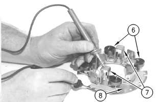
Typical example of a brush holder test (6) Brush spring (7) Brush holder (8) Brush holder plate |
|
- Check the brush springs (6) for damage or rust. If necessary, replace the brush springs.
- Place the multimeter in the "20M Ohms" range. Touch one meter lead to each positive brush holder (7) and the other lead to brush holder plate (8). Check the three positive brush holders (7).
- Each multimeter reading should be greater than 100,000 Ohms. A meter reading of "0.10" or a value that is greater is acceptable.
- If the meter reading is less than 100,000 Ohms, the brush holder is grounded. The brush holder must be replaced.
Brush Length Check
 > |
|
| Illustration 2 | g00801226 |
|
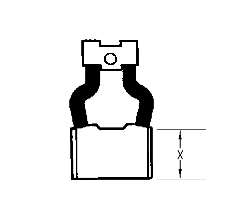
Typical example of a brush length measurement (X) Brush length |
|
- Measure brush length (X) for wear. The new brush length is 23.0 mm (0.91 inch). The minimum brush length is 10.0 mm (0.40 inch).
- If the brushes are worn below the minimum length, replace the brush holder.
Pinion Clearance - Adjust
SMCS - 1453-025
37-MT Starting Motors (12 Volt Systems)
 |
|
| Illustration 1 | g00810014 |
|
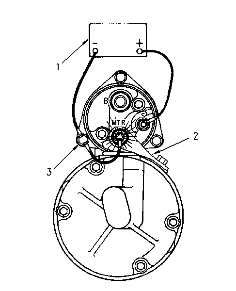
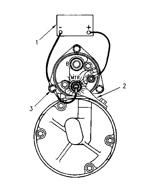
Connections for pinion clearance check for 12 volt system (1) Battery (2) Starting motor (3) Solenoid mounting bolt |
|
 |
|
| Illustration 2 | g00810097 |
|
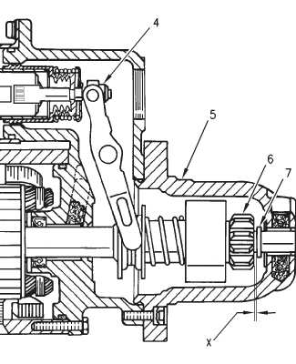
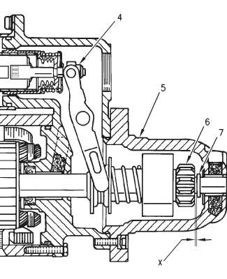
(4) Adjustment nut (5) Pinion drive housing (6) Pinion (7) Retainer (X) Pinion clearance |
|
When the solenoid is installed, make an adjustment of the pinion clearance. The adjustment should be made with the starting motor removed.
- Disconnect the terminal connector for the starting motor "MTR" from the solenoid.
- Connect the battery to the solenoid per Illustration 1. The illustration shows a 12 volt system with a battery that is connected in series to a starting motor. Connect the negative side of the battery cable to the solenoid mounting bolt (3) of the starting motor (2).
- Temporarily, touch a wire from the solenoid mounting bolt terminal (3) to the "MTR" terminal. The pinion will shift to the crank position and the pinion will stay there until the battery is disconnected.
- Push the pinion toward the commutator in order to remove free movement.
- Measure the clearance (X) from the pinion (6) to the pinion drive housing (5). Pinion clearance (X) must be 1.0 ± 0.8 mm (0.04 ± 0.03 inch).
- If the clearance is not correct, remove the plug on the shift lever housing (5). Turn the adjustment nut (4) until the clearance is correct. Turning the nut clockwise will decrease the clearance (X) .
Note: The plunger may turn when the adjustment nut (4) is being turned. If the plunger turns, disconnect the battery from the solenoid. Remove the solenoid from the starting motor. Hold the plunger from turning and adjust the nut (4). This procedure may need to be performed several times until the correct clearance is obtained.
- Disconnect the batteries and install the plug into the shift lever housing (5) .
37-MT Starting Motors (24 Volt Systems)
|
|
|
| Illustration 3 | g00810110 |
|
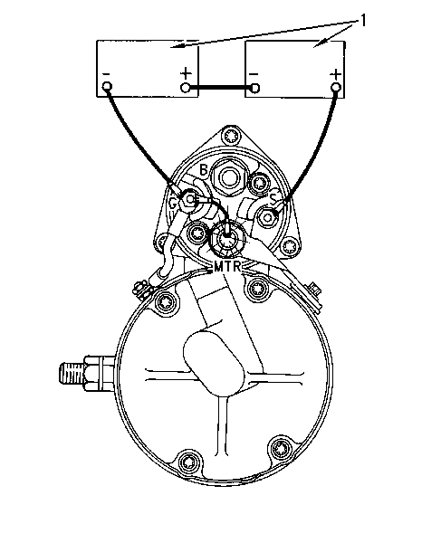
Connections for pinion clearance check for 24 volt system (1) Battery |
|
 |
|
| Illustration 4 | g00810097 |
|
(4) Adjustment nut (5) Pinion drive housing (6) Pinion (7) Retainer (X) Pinion clearance |
|
When the solenoid is installed, make an adjustment of the pinion clearance. The adjustment should be made with the starting motor removed.
- Disconnect the terminal connector of the starting motor "MTR" from the solenoid.
- Connect the battery to the solenoid per Illustration 3. The Illustration shows a 24 volt system with two 12 volt batteries that are connected in series to a starting motor. Connect the positive side of the battery cable to the "S" terminal. Connect the negative side of the battery cable to the "G" terminal of the starting motor.
- Temporarily, touch a wire from the "G" terminal to the "MTR" terminal. The pinion (6) will shift to the crank position and the pinion will stay there until the battery is disconnected.
- Push the pinion toward the commutator in order to remove free movement.
- Measure the clearance (X) from the pinion (6) to the pinion drive housing (5). Pinion clearance (X) must be 1.0 ± 0.8 mm (0.04 ± 0.03 inch).
- If the clearance is not correct, remove the plug on the shift lever housing (5). Turn the adjustment nut (4) until the clearance is correct. Turning the nut clockwise will decrease the clearance (X) .
Note: The plunger may turn when the adjustment nut (4) is being turned. If the plunger turns, disconnect the battery from the solenoid. Remove the solenoid from the starting motor. Hold the plunger from turning and adjust the nut (4). This procedure may need to be performed several times until the correct clearance is obtained.
- Disconnect the batteries (1) and install the plug into the shift lever housing (5) .
41-MT Starting Motors (12 Volt Systems)
 |
|
| Illustration 5 | g00810014 |
|
Connections for pinion clearance check for 12 volt system (1) Battery (2) Starting motor (3) Solenoid mounting bolt |
|
 |
|
| Illustration 6 | g00810097 |
|
(4) Adjustment nut (5) Pinion drive housing (6) Pinion (7) Retainer (X) Pinion clearance |
|
When the solenoid is installed, make an adjustment of the pinion clearance. The adjustment should be made with the starting motor removed.
- Disconnect the terminal connector for the starting motor (MTR) from the solenoid.
- Connect the battery to the solenoid per Illustration 5. The Illustration shows a 12 volt system with a battery that is connected in series to a starting motor. Connect the negative side of the battery cable to the solenoid mounting bolt (3) of the starting motor.
- Temporarily, touch a wire from the solenoid mounting bolt terminal (3) to the "MTR" terminal. The pinion will shift to the crank position and the pinion will stay there until the battery is disconnected.
- Push the pinion (6) toward the commutator in order to remove free movement.
- Measure the clearance (X) from the pinion (6) to the pinion drive housing (5). Pinion clearance (X) must be 4.57 ± 0.76 mm (0.18 ± 0.03 inch).
- If the clearance is not correct, remove the plug on the shift lever housing (5). Turn the adjustment nut (4) until the clearance is correct. Turning the nut clockwise will decrease the clearance (X) .
Note: The plunger may turn when the adjustment nut (4) is being turned. If the plunger turns, disconnect the battery from the solenoid. Remove the solenoid from the starting motor. Hold the plunger from turning and adjust the nut (4). This procedure may need to be performed several times until the correct clearance is obtained.
- Disconnect the batteries (1) and install the plug into the shift lever housing (5) .
41-MT Starting Motors (24 Volt Systems)
 |
|
| Illustration 7 | g00810101 |
 |
|
| Illustration 8 | g00716455 |
|
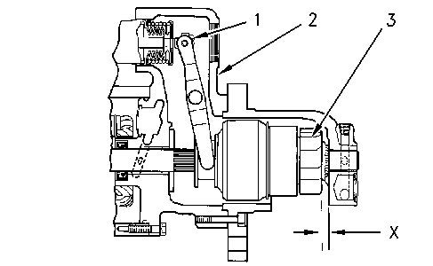
Pinion clearance check (1) Adjustment nut (2) Pinion drive housing (3) Pinion (X) Pinion clearance |
|
When the solenoid is installed, make an adjustment of the pinion clearance. The adjustment should be made with the starting motor removed.
- Disconnect the starting motor negative wire from the "G" ground terminal of the solenoid.
- Connect the batteries to the solenoid per Illustration 7. The Illustration shows a 24 volt system with two 12 volt batteries that are connected in series to a starting motor. Connect four 8 volt batteries in series for a 32 volt system. Connect eight 8 volt batteries in series for a 64 volt system. Connect the positive side of the battery cable to the "S" terminal of the starting motor solenoid. Connect the negative side of the battery cable to the "G" terminal of the starting motor.
- Temporarily, touch a wire from the "G" terminal to the "MTR" terminal. The pinion will shift to the crank position and the pinion will stay there until the battery is disconnected.
- Push the pinion toward the commutator in order to remove free movement.
- Measure the clearance (X) from the pinion (3) to the pinion drive housing (2). Pinion clearance (X) must be 9.10 ± 0.8 mm (0.36 ± 0.03 inch).
- If the clearance is not correct, remove the plug on the shift lever housing (2). Turn the adjustment nut (1) until the clearance is correct. Turning the nut clockwise will decrease the clearance (X) .
Note: The plunger may turn when the adjustment nut (1) is being turned. If the plunger turns, disconnect the battery from the solenoid. Remove the solenoid from the starting motor. Hold the plunger from turning and adjust the nut (1). This procedure may need to be performed several times until the correct clearance is obtained.
- Disconnect the batteries and install the plug into the shift lever housing (2) .
42-MT Starting Motors (12 Volt Systems)
 |
|
| Illustration 9 | g00810014 |
|
Connections for pinion clearance check for 12 volt system (1) Battery (2) Starting motor (3) Solenoid mounting bolt |
|
 |
|
| Illustration 10 | g00810097 |
|
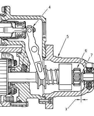
(4) Adjustment nut (5) Pinion drive housing (6) Pinion (7) Retainer (X) Pinion clearance |
|
When the solenoid is installed, make an adjustment of the pinion clearance. The adjustment should be made with the starting motor removed.
- Disconnect the terminal connector of the starting motor (MTR) from the solenoid.
- Connect the battery to the solenoid per Illustration 9. The Illustration shows a 12 volt system with a battery that is connected in series to a starting motor. Connect the negative side of the battery cable to the solenoid mounting bolt (3) of the starting motor.
- Temporarily, touch a wire from the solenoid mounting bolt terminal (3) to the "MTR" terminal. The pinion (6) will shift to the crank position and the pinion will stay there until the battery is disconnected.
- Push the pinion toward the commutator in order to remove free movement.
- Measure the clearance (X) from the pinion (6) to the pinion drive housing (5). Pinion clearance (X) must be 9.10 ± 0.8 mm (0.36 ± 0.03 inch).
- If the clearance is not correct, remove the plug on the shift lever housing (5). Turn the adjustment nut (4) until the clearance is correct. Turning the nut clockwise will decrease the clearance (X) .
Note: The plunger may turn when the adjustment nut (4) is being turned. If the plunger turns, disconnect the battery from the solenoid. Remove the solenoid from the starting motor. Hold the plunger from turning and adjust the nut (4). This procedure may need to be performed several times until the correct clearance is obtained.
- Disconnect the batteries and install the plug into the shift lever housing.
42-MT Starting Motors (24 Volt Systems)
 |
|
| Illustration 11 | g00810101 |
|
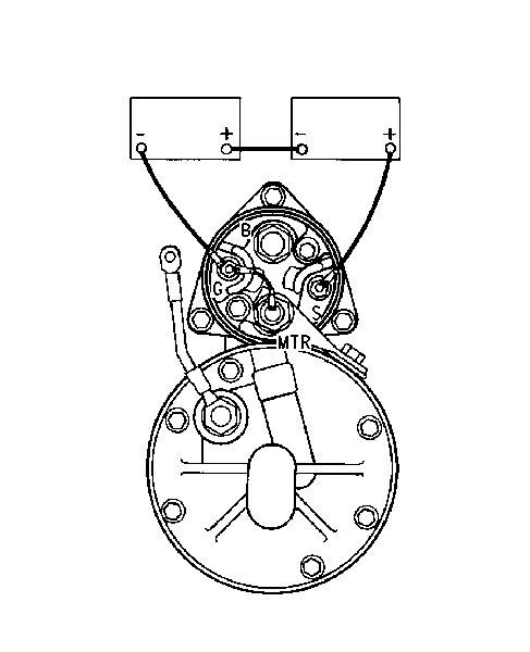
Connections for pinion clearance check for 24 volt system |
|
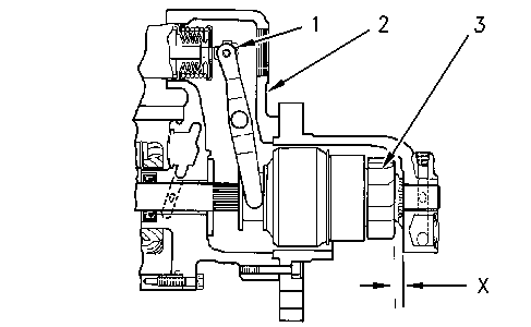 |
|
| Illustration 12 | g00716455 |
|
Pinion clearance check (1) Adjustment nut (2) Pinion drive housing (3) Pinion (X) Pinion clearance |
|
When the solenoid is installed, make an adjustment of the pinion clearance. The adjustment should be made with the starting motor removed.
- Disconnect the starting motor negative wire from the "G" ground terminal of the solenoid.
- Connect the batteries to the solenoid per Illustration 11. The Illustration shows a 24 volt system with two 12 volt batteries that are connected in series to a starting motor. Connect four 8 volt batteries in series for a 32 volt system. Connect eight 8 volt batteries in series for a 64 volt system. Connect the positive side of the battery cable to the "S" terminal of the starting motor solenoid. Connect the negative side of the battery cable to the "G" terminal of the starting motor.
- Temporarily, touch a wire from the "G" terminal to the "MTR" terminal. The pinion will shift to the crank position and the pinion will stay there until the battery is disconnected.
- Push the pinion toward the commutator in order to remove free movement.
- Measure the clearance (X) from the pinion to the pinion drive housing. Pinion clearance (X) must be 9.10 ± 0.8 mm (0.36 ± 0.03 inch).
- If the clearance is not correct, remove the plug on the shift lever housing (2). Turn the adjustment nut (1) until the clearance is correct. Turning the nut clockwise will decrease the clearance (X) .
Note: The plunger may turn when the adjustment nut (1) is being turned. If the plunger turns, disconnect the battery from the solenoid. Remove the solenoid from the starting motor. Hold the plunger from turning and adjust the nut (1). This procedure may need to be performed several times until the correct clearance is obtained.
- Disconnect the batteries and install the plug into the shift lever housing.
C27 and C32 Engines for Caterpillar Built Machines - SENR9937
Batería - Probar
SMCS - 1401-081
La mayoría de las pruebas del sistema eléctrico se pueden realizar en el motor. El material aislante del cableado tiene que estar en buenas condiciones. Las conexiones de los cables deben estar limpias y los cables deben estar ajustados.
 |
|
No desconecte nunca de la batería ningún circuito unitario de carga o cable del circuito de la batería cuando se opere la unidad de carga. De producirse una llama se puede provocar una explosión debido a la mezcla inflamable de vapor de hidrógeno y oxígeno desprendida del el electrólito por las salidas de la batería. Como consecuencia se pueden producir lesiones personales. |
El circuito de la batería es una carga eléctrica en la unidad de carga. La carga es variable debido al estado de carga de la batería.
| ATENCION |
|---|
|
La unidad de carga se dañará si las conexiones entre la batería y la unidad de carga se rompen mientras se está cargando la batería. Pueden ocurrir daños porque la carga de la batería se pierde y porque hay un aumento en el voltaje de carga. Este alto voltaje dañará la unidad de carga, el regulador y otros componentes eléctricos. |
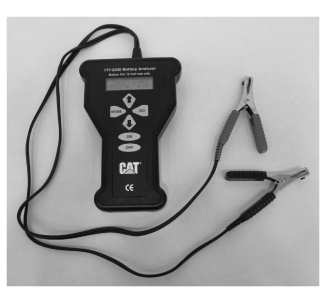 |
|
| Ilustración 1 | g02231076 |
| 177-2330 Analizador de baterías | |
Consulte el Manual de Operación, NEHS0764, "Using the 177-2330 Battery Analyzer" para obtener instrucciones detalladas sobre el uso del 177-2330 Analizador de Baterías
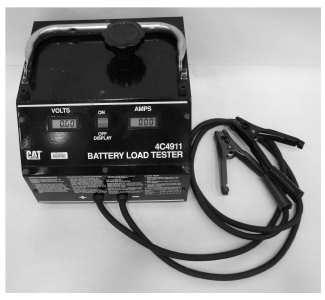 |
|
| Ilustración 2 | g02231156 |
| 4C-4911 Probador de Carga de Batería | |
Consulte el Manual de Operación, SEHS9249, "Use of 4C-4911 Battery Load Tester for 6 V, 8 V, and 12 V Lead Acid Batteries" para obtener instrucciones detalladas sobre el uso del 4C-4911 Probador de Carga de Batería.
Utilice el 4C-4911 Probador de Carga de Batería o el 177-2330 Analizador de Baterías para probar una batería que no mantiene la carga cuando está activa. El 4C-4911 Probador de Carga de Batería y el 177-2330 Analizador de Baterías son unidades portátiles. El 4C-4911 Probador de Carga de Batería o el 177-2330 Analizador de Baterías se pueden utilizar en condiciones de campo y a altas temperaturas.
- Revise el voltaje de la batería.
- Si el voltaje está por encima de los 12,45 V, entonces, la batería está en buenas condiciones.
- Si el voltaje de la batería está por debajo de los 12 V, la batería se debe reemplazar.
- Si el voltaje de la batería está entre 12 V y 12,3 V, haga funcionar la máquina a aceleración media durante 60 minutos y vuelva a revisar el voltaje de batería. Si el voltaje no está por encima de los 12,45 V, entonces, reemplace la batería.
- Si el voltaje de la batería está entre 12.3 V y 12,45 V, haga funcionar la máquina a aceleración media durante 30 minutos y vuelva a revisar el voltaje de batería. Si el voltaje no está por encima de los 12,45 V, entonces, reemplace la batería.
- Si el voltaje está por encima de los 12,45 V, entonces, la batería está en buenas condiciones.
Sistema de carga - Probar
SMCS - 1406-081
El estado de carga de la batería en cada inspección regular indicará si el sistema de carga está funcionando correctamente. Es necesario un ajuste cuando la batería está constantemente en una condición de carga baja o se necesita una gran cantidad de agua. Una gran cantidad de agua sería más de una onza de agua por una celda por una semana o por cada 100 horas de servicio.
Se prefiere la prueba en el motor de los componentes del sistema de carga, incluyendo los cables y otros componentes que forman parte permanente del sistema. La prueba fuera del motor o en el banco de la operación de los componentes del sistema de carga es aceptable sólo como último recurso. Esta prueba dará una indicación de las reparaciones que se necesiten. Una vez que se hayan efectuado las reparaciones, pruebe el sistema de carga para verificar que cumple con las especificaciones.
Herramientas de prueba para el sistema de carga
| Herramientas necesarias | ||
| Número de pieza | Nombre de la pieza | Cantidad |
| 225-8266 | Grupo de amperímetro | 1 |
| 237-5130 o 146-4080 |
Grupo de Multímetro Digital o Grupo de Multímetro Digital |
1 |
Grupo de Amperímetro 225-8266
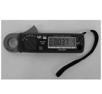 |
|
| Ilustración 1 | g02231196 |
| Grupo de Amperímetro 225-8266 | |
El Grupo de Amperímetro 225-8266 es portátil. Este amperímetro es un instrumento autocontenido que mide las corrientes eléctricas sin interrumpir el circuito y sin alterar el material aislante del conductor.
El amperímetro contiene una pantalla digital que se utiliza para supervisar la corriente directamente en un intervalo comprendido entre 1 y 1200 amperios. Para ver las lecturas actuales de menos de 1 amperio, use la pantalla del multimetro. Para leer la pantalla del multimetro, conecte un Cable 6V-6014 entre el multimetro digital y el amperímetro. El amperímetro envía entonces la medición de la corriente a la pantalla del multímetro.
Una palanca abre las mordazas del amperímetro sobre un conductor. El diámetro del conductor no puede ser mayor de 19 mm (0,75 pulg).
Las mordazas cargadas por resorte se cierran sobre el conductor para medir la corriente. El amperímetro es controlado por un interruptor de disparo. El interruptor de disparo se puede trabar en la posición de ENCENDIDO o de APAGADO.
Después de haber puesto el interruptor de disparo en la posición de ENCENDIDO, la lectura aparece en la pantalla digital durante 5 segundos. Esto mide con precisión las corrientes en áreas de acceso limitado. Por ejemplo, estas áreas incluyen las que están fuera de la vista del operador. Para la operación de corriente continua, el amperímetro contiene un control cero. Las pilas dentro de la manilla suministran la corriente.
Nota: Consulte el Manual del Usuario para obtener más información acerca la utilización del Grupo de Amperímetro 225-8266.
Grupo de Multímetro Digital 237-5130 o Grupo de Multímetro Digital 146-4080
 |
|
| Ilustración 2 | g02231214 |
| Grupo de Multímetro Digital 237-5130 o Grupo de Multímetro Digital 146-4080 | |
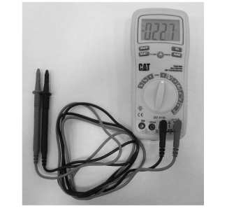
El Grupo de Multímetro Digital 237-5130 o el Grupo de Multímetro Digital 146-4080 es una herramienta de servicio portátil que se puede sostener con la mano y que tiene una pantalla digital. Este multímetro tiene una protección adicional contra los posibles daños en aplicaciones de campo. El multímetro está equipado con 7 funciones y 29 intervalos. El Grupo de Multímetro Digital 237-5130 o el Grupo de Multímetro Digital 146-4080 tiene un indicador de ohmios instantáneos. Este indicador permite comprobar la continuidad para una inspección rápida de los circuitos. También puede usarse para localizar y solucionar problemas de condensadores que tengan valores pequeños.
Nota: Consulte el manual proporcionado por el proveedor para obtener más información sobre la utilización del Grupo de Multímetro Digital 237-5130. Consulte el Manual de Operación, NEHS0678 para obtener información completa sobre el uso del Grupo de Multímetro Digital 146-4080.
Sistema de carga
Para comprobar la salida correcta del alternador, vea el módulo de Especificaciones. Consulte la Instrucción Especial, REHS0354, "Localización y solución de problemas del sistema de carga". Si el número de pieza para el alternador que se va a probar no está indicado en la Instrucción Especial, consulte el manual de Especificaciones apropiado para ver la información que se necesita para probar el alternador.
Antes de empezar las pruebas en el motor, se debe comprobar el sistema de carga y la batería de acuerdo con los pasos siguientes.
- La batería debe estar cargada al menos un 75 por ciento (peso específico de 1,225) con respecto a la carga completa. La batería debe estar bien sujeta. El retén no debe ejercer un esfuerzo demasiado grande sobre la batería.
- Los cables entre la batería, el motor de arranque y la conexión a tierra del motor deben ser del tamaño correcto. Los alambres y los cables no deben tener corrosión. Los alambres y los cables deben tener las abrazaderas de soporte del cable para evitar tensiones en las conexiones de baterías (terminales).
- Los cables, empalmes, interruptores e instrumentos del tablero que tengan una relación directa con el circuito de carga deben proporcionar un control adecuado del circuito.
- Inspeccione los componentes de accionamiento de la unidad de carga para asegurarse de que no tengan grasa ni aceite. Cerciórese de que los componentes de mando pueden operar la unidad de carga.
- Compruebe la tensión de la correa para la polea del alternador. Consulte la Tabla de Tensión de la Correa para informarse de la tensión correcta de la correa.
Alternador
La velocidad de carga del alternador debe comprobarse cuando el alternador está cargando demasiado la batería. La velocidad de carga del alternador debe comprobarse cuando el alternador no esté cargando suficiente la batería. Consulte en el módulo de Especificaciones todas las especificaciones de pruebas para los alternadores y reguladores.
No se puede efectuar un ajuste para cambiar el régimen de carga de los reguladores de los alternadores. Si el régimen de carga no es correcto, es necesario reemplazar el regulador.
Cómo apretar la tuerca de la polea del alternador

Apriete la tuerca que sujeta la polea con las herramientas mostradas. Vea los valores de par en el manual Especificaciones.
Regulador
El regulador de voltaje es un interruptor electrónico de estado sólido. El regulador siente el voltaje del sistema y controla la corriente del campo al alternador. El voltaje de salida del alternador proveerá las necesidades de la batería. El voltaje de salida también proveerá a los demás componentes en el sistema eléctrico.
Sistema de arranque eléctrico - Probar
SMCS - 1450-081
La mayoría de las pruebas del sistema eléctrico se pueden realizar en el motor. El aislamiento de los cables tiene que estar en buenas condiciones. Las conexiones tienen que estar limpias y apretadas. La batería tiene que estar completamente cargada. Si la prueba del motor en marcha muestra un defecto en un componente, quite el componente para efectuar pruebas adicionales.
El sistema de arranque consta de los siguientes componentes:
- Interruptor con llave
- Solenoide del motor de arranque
- Motor de arranque
| Herramientas necesarias | ||
| Número de pieza | Nombre de la pieza | Cant. |
| 237-5130 9 146-4080 |
Multímetro digital | 1 |
 |
|
| Ilustración 1 | g00283566 |
|
Multímetro digital 237-5130 o Multímetro digital 146-4080 |
|
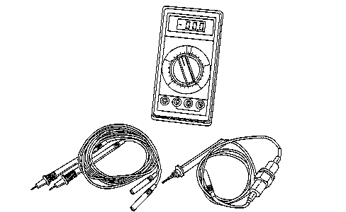
El Multímetro Digital 237-5130 o el Multímetro digital 146-4080 es una herramienta de servicio portátil con una pantalla digital, que es completamente portátil. Este multímetro tiene una protección adicional contra los posibles daños en aplicaciones de campo. El multímetro está equipado con 7 funciones y 29 intervalos. El Multímetro digital 237-5130 o el Multímetro digital 146-4080 tiene un indicador de ohmios instantáneos. Este indicador permite comprobar la continuidad para efectuar una inspección rápida de los circuitos. También puede usarse para localizar fallas de condensadores que tengan valores pequeños.
Nota: Consulte la Publicación Especial, NENG2500, "Catálogo de herramientas de servicio del distribuidor de Caterpillar" para obtener información sobre el Multímetro Digital 237-5130. Consulte el Manual de Operación, NEHS0678para obtener información completa sobre el uso del Multímetro digital 46-4080.
Use el multímetro en la gama de VCC para localizar los componentes del sistema de arranque que no funcionen.
Mueva el interruptor de control de arranque para activar los solenoides de arranque. Se puede oír la operación del solenoide de arranque a medida que los piñones de los motores de arranque se engranen con la corona del volante del motor.
Si no funciona un solenoide de un motor de arranque, es posible que la corriente de la batería no llegue al solenoide. Sujete un terminal del multímetro al terminal de conexión del cable de la batería en el solenoide. Ponga el otro terminal del multímetro en contacto con una buena conexión a tierra. Una lectura igual a cero indica que hay un circuito interrumpido procedente de la batería. Es necesario efectuar más pruebas cuando exista una lectura de voltaje en el multímetro.
La operación del solenoide también cierra el circuito eléctrico al motor. Conecte un terminal del multímetro a la conexión del terminal del solenoide que está asegurada al motor. Ponga el otro terminal del multímetro en contacto con una buena conexión a tierra. Active el solenoide de arranque y fíjese en el multímetro. Si se indica un voltaje de la batería es que el problema está en el motor. El motor debe quitarse para efectuar pruebas adicionales. Una lectura de cero en el multímetro indica que los contactos del solenoide no se cierran. Esto significa que se debe reparar el solenoide o ajustar el espacio libre del piñón del motor de arranque.
Efectúe una prueba. Conecte un terminal del multímetro a la conexión de terminales del cable pequeño en el solenoide y sujete el otro terminal a la conexión de tierra. Fíjese en el multímetro y active el solenoide de arranque. Una lectura de voltaje muestra que el problema está en el solenoide. Una lectura de cero indica que el problema está en el interruptor de arranque o en los cables del mismo.
Sujete un terminal del multímetro al interruptor de arranque en la conexión terminal del cable de la batería. Conecte el otro cable a una conexión a tierra en buenas condiciones. Una lectura cero indica un circuito interrumpido procedente de la batería. Compruebe el disyuntor y las conexiones. Si se indica un voltaje, el problema está en el interruptor de arranque o en los cables del mismo.
Los motores de arranque que operan con demasiada lentitud pueden tener una sobrecarga debido a una fricción excesiva en el motor que se arranca. La operación lenta de los motores de arranque también puede ser causada por un cortocircuito, conexiones flojas y suciedad en los motores.
El problema con el sistema de arranque puede ser causado por la batería o por problemas del sistema de carga. Si se sospecha que hay problemas en el sistema de arranque, consulte el Manual de Servicio, SENR3860, "Motores de Arranque de la Serie MT". Esta publicación contiene los métodos de localización y solución de problemas para el sistema de arranque, procedimientos de prueba y especificaciones.